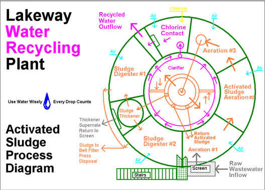
How does the Activated Sludge Water Recycling Plant work?
Lakeway MUD (LMUD) recycles all of its customer’s wastewater for landscape irrigation purposes. Using the five senses, the quality of our reuse water after treatment is indistinguishable from our drinking water. The following is a brief description of the wastewater treatment process: Wastewater from the collection system is pumped through a fine screen to remove material that could plug or harm downstream treatment equipment. The wastewater then enters aeration chamber #1, where it is mixed with activated sludge recirculated from the floor of the clarifier-settling basin.
Activated sludge is a “soup” of microorganisms that use the organics in the wastewater as food. This dynamic population of microbes removes the soluble organics from the wastewater. The microbes are not added to the wastewater, but are grown from those already present in some numbers. They are typically found in rich garden compost. The ones that proliferate are the particular microbes that are best suited to grow on the materials in the wastewater. They then become dominant in the activated sludge population. This is classic Darwinian natural selection of the best organisms to fill a niche. What we have to do is provide the proper environment, rich in oxygen, and the organic substrate “food,” then a natural wet compost process develops. Microbes that do not find suitable conditions for growth just die. Those that do not proliferate may survive in low numbers until they are killed or removed as described below. Human disease-causing agents do not fare well in the activated sludge process.
The microbe and wastewater mixture sequentially passes to aeration chamber #2, #3 and #4, and then transfers to the clarifiers. In each chamber, there is less “food” available as the microbes convert the organics to maintain respiration and growth. The clarifier uses gravity to separate the microbes as well as other solids from the water. This leaves only clear, clean water at the surface. The clarified water flows over peripheral weir troughs and then transfers to the filters. The filters use dual media granular particles of anthracite and silica sand to strain fine particles not retained in the clarifiers. The filtered water enters a chamber where chlorine is added to kill any remaining microbes before it flows to the storage ponds for reuse. Chlorine is the same disinfectant we use in our drinking water; it is very effective at killing any disease-causing agents.
Unlike anaerobic (septic system) microbes, aerobic organisms do not produce unpleasant odors. Activated sludge microbes are aerobic organisms and, therefore, require oxygen to thrive. High-volume compressors provide this oxygen transfer from air, by bubbling it through the water. The rising air bubbles also mix the aeration basins to bring the microbes in contact with the organics in the wastewater. The hydraulic contact time for the wastewater with the microbes is about 12 hours, while the microbe system residence time varies between eight and 12 days. This lengthy time is achieved through continual recirculation of the activated sludge.
The conversion of organic material to microbes produces clean water but also produces more activated sludge microbes. This excess sludge is removed from the clarifier and transferred to the sludge digester. The controlled rate of removal determines the average age of the microbes and is the primary mechanism to control activated sludge quality. The excess sludge is thickened and aerated in aerobic digesters, which allows the microorganisms to metabolize remaining organics and then stabilize. Water separated from the sludge in the thickener returns to the beginning of the process for retreatment. Sludge stabilization is achieved after an additional 10 to 15 days of sludge retention in the digesters. Stabilized sludge is no longer active and will not produce odors, even if not aerated. The belt filter press “dewaters” the stabilized sludge to a Play-Doh consistency, which then is delivered to a landfill. Belt press filtrate and belt wash water also return to the beginning of the process for retreatment. The site irrigation and in-plant uses are all recycled water.
We recycle all of our wastewater. Finished water for reuse is transferred to storage in one of our ponds. The ponds have pumps that distribute water to the golf courses and to our 25 other reuse customers for landscape irrigation. None of the water is returned to Lake Travis.
Palos Verdes Water Recycling Plant
The Palos Verdes Water Recycling Plant (WRP) takes wastewater from the collection system via three 25 HP submersible pumps with variable speed drives (VFD). The Supervisory Control and Data Acquisition (SCADA) configurable VFD controls allow a more constant flow to the rotary fine screen that removes material larger than one tenth of an inch. Screenings are landfilled.
Screened wastewater transfers to aeration at up to four points, one in each of the four aeration basins. The aeration basins can operate in plug flow, step feed, or contact stabilization modes. Up to two of the four fine-bubble, diffused air basins can be taken out of service for maintenance. Up to three 75 HP blowers provide air. Return activated sludge (RAS) enters aeration at any combination of the same four locations as influent. Pairs of aeration basins can operate in parallel or all four can operate in series. Generally, we operate all four basins in series with screened wastewater flow and return sludge flow to the first two aeration basins. Mixed liquor from aeration transfers to two 44’ clarifiers via a flow splitter that can also isolate either one for maintenance. The clarifiers feature outboard weir troughs, flat bottom hydraulic-differential sludge withdrawal collectors, surface skimming and intermittent peripheral chlorination at the weirs for algae control. SCADA controls flow-paced clarifier sludge return to aeration by up to three 7.5 HP VFD centrifugal pumps.
Clarifier overflow transfers to two parallel flow granular media traveling bridge backwash filters. The filters’ inlet is one of several possible chlorination points. Each filter is sized for the full plant design flow. Turbidity meters sample filter feed and filter outlet and report to SCADA. The filter controls are programmable logic controllers (PLC) configurable via SCADA via Ethernet Local Area Network (LAN). The chlorine residual meter samples filtered water and reports to SCADA. Filtered water transfers to the chlorine contact basins, which are two parallel, serpentine, over-under, baffled basins. For maintenance, either basin drains to the lift station with sloped bottoms. V-notch weirs measure flow from the chlorine contact basins to the pump chamber. Level sensors report flow rate and flow total to SCADA. The pump chamber has three 125 HP pumps that move reuse water directly to the reuse distribution system or to storage, depending on the short and long-term storage conditions at the time. Two smaller pumps maintain pressure in the plant non-potable water (NPW) system. The plant uses NPW for wash down, belt filter press wash water and landscape irrigation.
Waste activated sludge diverts from the RAS system to the aerobic digester via SCADA controlled valves. The one-meter belt filter press dewaters digested sludge for landfill. The disinfectant is liquid hypochlorite solution delivered in bulk to two 5000 gallon tanks. SCADA controls automatically transfer to a 500 gallon day-tank and flow paced metering system featuring tubing pumps. On-line measurement of filtered water chlorine residual biases flow pacing for better dosing control.
The LAN consists of four PLCs and two operator workstations. The LAN communicates with a Wide Area Network (WAN) via radio modems using Ethernet protocol. The WAN consists of various storage and pumping sites in the reuse distribution system, the Trophy WRP, as well as the potable water production and distribution system. This WAN allows all data from 14 different PLCs to be available to both water and wastewater system operators at six different workstations, as well as from the operator’s home PC.
We recycle all of our wastewater. Finished water for reuse is transferred to storage in one of our ponds. The ponds have pumps that distribute water to the golf courses and to our 25 other reuse customers for landscape irrigation. None of the water is returned to Lake Travis.
Reduce the Risk of Wastewater Backup in Your Home
On occasion, a residential wastewater service line or a wastewater collection pipeline serving your neighborhood may become blocked. If it happens to you, it is a disaster. It could cause wastewater to back up into your home with very unpleasant results and costly cleanup expenses.
In Lakeway, the risk of backups is increased by our topographical features, with some homes being below grade. Pipeline blockages can be caused by a number of things such as tree roots, grease buildup and improper disposal of objects. While all of the causes of wastewater backups cannot be eliminated, it is possible to minimize their impact. LMUD is installing a backflow relief valve for all homes, where possible. This valve easily installs on most wastewater cleanout valves. The cleanout is normally in front of your house, between the house and the street. The backflow relief valve is pressure-activated and is designed to discharge a backup outside, rather than inside your house. It may not eliminate all backups, but it should work in most circumstances. You or your plumber can easily install the relief valve. It is simple, reliable and inexpensive.
In addition, LMUD is committed to cleaning all of the wastewater collection pipelines every few years. You may see a large truck called a Vactor that features huge suction pipes and tanks as well as a hydraulic hose. These machines clean wastewater pipelines and manholes. After cleaning, the pipelines are inspected internally using closed-circuit television cameras. Wherever roots or other problems are revealed, the issue is corrected either by digging it up and repairing it or by remote internal repairs.
This program includes repairs to our manholes and other wastewater collection structures. The program has the added benefit of reducing rainwater inflow and groundwater infiltration into the wastewater system. For this reason, we call this our Infiltration and Inflow, or I&I, program. This program reduces the loading on the collection system and at the water recycling plant, and keeps our wastewater collection infrastructure well-maintained and operational. It also reduces the risk of wastewater backups in your home.
 You are now being redirected to the WaterSmart page.